.png)
電
用
光
發
美
好
共
建
Eight technological processes of photovoltaic modules + common quality problems!
_cc781905-5cde-3194-bb3b-136bad5d_cf58d_ _cc781905-5cde-3194-bb3d_cf58d_ _cc781905-5cde-3194-bb3d_cf58d_ _cc781905-5cde-3194-bb3d_cf58d_ Single-piece welding process of photovoltaic cells , cell string welding, module stacking, module lamination, frame installation and junction box installation, finished product testing and packaging storage and other processes. Each process is interlinked, so the level of craftsmanship of each process directly affects the quality and grade of the product.
Next, let's take a closer look at the eight major processes of photovoltaic module processing and the common quality problems of photovoltaic modules.
1. Processing technology of photovoltaic modules
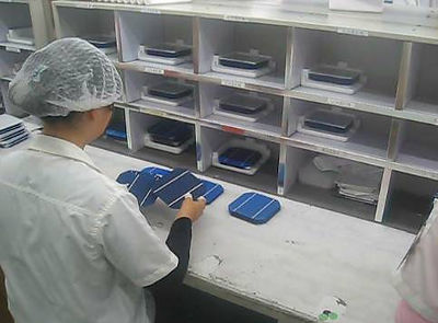
The first process is cell inspection
As the main raw material for photovoltaic module processing, the performance of the cell directly determines the quality of the photovoltaic module. Therefore, in addition to its appearance inspection, it is also necessary to test the output current, output voltage, output voltage, etc. Output power and other parameters, its test is mainly completed through professional instruments and equipment.
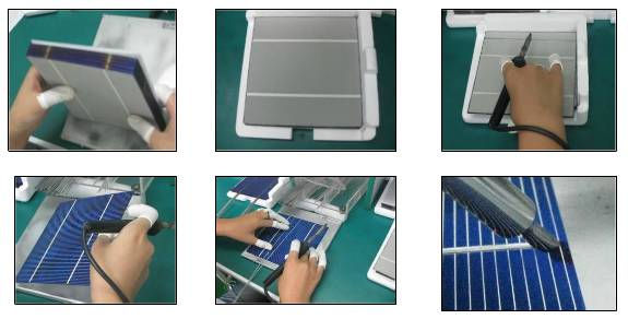
_cc781905-5cde-3194-bb3d_cf58d_The second process is the single-piece welding of the cell
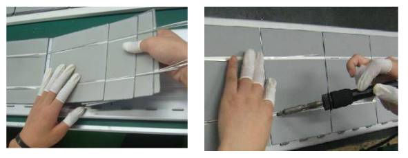
_cc781905-5cde-3194-bb3d_cf58d_The third process is the string welding of cells
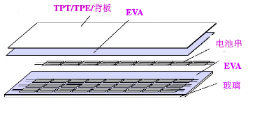
_cc781905-5cde-3194-bb3d_cf58d_The fourth step is lamination
Laminate the battery strings, glass, cut EVA, and back sheets according to a certain level, ready for lamination. Glass is coated with a layer of agent in advance to increase the bonding strength of glass and EVA. When laying, ensure the relative position of the battery string and glass and other materials, adjust the distance between the batteries, and lay a good foundation for lamination. (Laying level: from bottom to top: glass, EVA, battery, EVA, backplane).
The 5th step is lamination
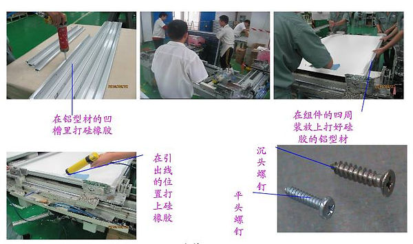
_cc781905-5cde-3194-bb3d_cf58d_The sixth process is framing
Apply silicone evenly in the grooves of the aluminum alloy frame, insert the components into the grooves of the aluminum alloy, and start the framing machine to complete the framing. Apply silicone evenly at the junction of TPT and aluminum alloy on the back of the module, apply silicone evenly on the back of the junction box of the corresponding specification and around the root of the lead wire, glue the junction box, and connect the leads to the junction box. Cure at room temperature and humidity.
_cc781905-5cde-3194-bb3d_cf58d_The seventh process is cleaning
_cc781905-5cde-3194-bb3d_cf58d_The eighth process is the finished component testing
Perform the test in accordance with the operating procedures of the solar module tester. First, calibrate the solar module tester with standard components in the same environment, and make calibration records. Put the photovoltaic modules to be tested, connect the positive and negative poles, and test the components. Through comparison and analysis, the electrical performance parameters of the components are calculated and recorded.
2. Analysis of common quality problems of photovoltaic modules
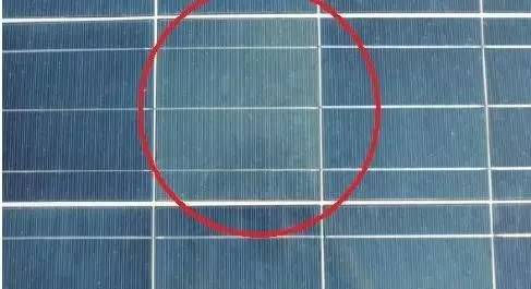
1. Cracked cell
Causes:
a. The battery is caused by external force during welding or handling.
b. The cells are not preheated at low temperature, and they expand and cause cracks after being suddenly exposed to high temperature in a short period of time.
c. The instantaneous temperature is too high during welding.
Component Impact
a. Cracks will affect the power attenuation of components.
b. Long-term cracks will lead to debris, hot spots and other phenomena that directly affect the performance of the module.
Precaution:
a. During the production process, avoid excessive collision of the cells by external forces.
b. During the welding process, the battery should be kept warm in advance, and the temperature of the soldering iron should meet the requirements.
c. The EL test strictly analyzes the black lines on each picture.
d. When there are cracks in the picture, open the back plate and EVA, and confirm with a flashlight. The hidden splinter should be replaced in time.
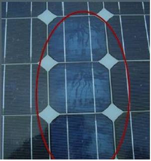
2. EVA undissolved
Causes:
a. EVA material expired.
b. The design of the heating process of the laminator (such as low temperature of the laminator, short lamination time, etc.) is unreasonable.
c. The cross-linking degree test failed to find out the correct process parameters of the EVA.
Precaution:
a. Strengthen the improvement of raw material suppliers and the inspection of raw materials.
b. Strictly control important parameters such as temperature and time of the laminator.
c. Do the cross-linking degree test as required, and control the cross-linking degree within 85%±5%.
3. Bubble
Causes:
a. There is a foreign object inside the assembly.
b. EVA expired.
c. Laminator failure: low vacuum, cracked sealing ring.
d. The parameters of the laminator are set abnormally.
e. Flux surface residue.
f. Welding of interconnection bars.
Component Impact
Component air bubbles can affect delamination and can seriously lead to scrap.
Precaution:
a. Improve the workshop production environment and check before lamination.
b. The EVA used should be within the shelf life, and those that cannot be used on the same day should be sealed and stored.
c. Adjust the parameters of the laminator when large-area bubbles burst.
d. Do a spot check on each shift of the laminator, observe the vacuum value up and down in time, check the condition of the sealing ring in time, and do a good job in daily maintenance.
e. EVA of different manufacturers has different lamination parameters, adjust the process in time.
f. Control the use of flux, and wipe the surface with alcohol if there is any residue.
g. Minimize the rework of cells on the stacking table as much as possible to prevent foreign objects from falling into and prevent secondary pollution.
h. The management personnel confirm the process value set by the laminator every day.
3. Black film
Causes:
a. The positive and negative interconnection bars are short-circuited.
b. Welding of interconnecting strips.
c. The diode of the junction box is reversely welded or the wiring is abnormal.
d. The external wiring of the test machine is abnormal.
Precaution:
a. Prevent solder residue on the edge of the cell during string welding.
b. Prevent virtual welding when the temperature is low.
c. Focus on checking images during the initial test.
d. If there is any abnormality after the final test, the frame should be folded and replaced.
e. Check the diode welding and lead welding of the junction box when it is black.
f. Check the external wiring of the tester.
4. Bad slag
Causes:
a. Tin dross remains during soldering.
b. There is tin dross on the bottom plate.
c. Welding is performed on the components when changing the film.
Precaution:
a. Clean up the tin pile on the tip of the soldering iron in time to prevent the tin slag from falling off during the welding operation.
b. Clean the bottom plate in time to prevent tin slag residue.
c. Do not replace solder cells on stacked modules.
d. Check whether there is tin slag residue on the cell in time after stringing.
5. Foreign body
Causes:
a. The foreign body sticks to the battery sheet when the welder is working.
b. Dirt on the welding bottom plate.
c. There is dirt on the glass bottom plate and EVA during lamination.
d. Hair, dirt, etc. fall on the battery sheet when the stacker is working.
e. Secondary pollution when replacing the film if the initial test is bad.
Precautions:
a. Welding and laminating personnel should dress according to regulations and wrap their hair in a clean cap.
b. When stacking personnel work, pay attention to checking the glass bottom plate and EVA contamination.
c. The welding table, welding bottom plate, welding turnover box and stacking table are cleaned regularly.
d. Regularly clean the area with wet dust mops in the welding room and lamination area to keep the ground free of foreign objects.
e. Personnel clean clothes should be cleaned regularly.
6. Split
Causes:
a. The gesture is too heavy when welding a single string.
b. When the interconnecting strips are welded, there are dots of tin piling and virtual welding, resulting in lamination cracks.
c. Laminating and laminating personnel touch and press the battery sheet with their hands when lifting the stacked battery sheet.
d. The quality of the battery itself is caused by cracks.
e. The pressure in the pressing stage of the laminator is large.
f. EVA is not flat (the bulge phenomenon is serious).
Component Impact
a. The partial failure of the lobes affects the power attenuation of the module.
b. The power attenuation or complete failure of a single cell affects the power attenuation of the module.
Precautions:
a. Lamination and lamination personnel should not touch the side cells when lifting the stacked cells.
b. Lamination and lamination personnel should avoid touching the crossbar on the trolley when lifting the stacked cells.
c. Welding personnel should prevent the abnormal phenomenon of surfacing and virtual welding during welding.
d. Carefully analyze each picture during the initial test to prevent hidden cracks from flowing into the lamination group.
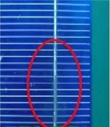
7. Welding ribbon offset (exposed white)
Causes:
a. During welding, the positioning of the interconnecting strips deviates from the position of the welding printed lines on the cell.
b. The starting point of the interconnection bar is crooked during operation, causing offset.
Precautions:
a. The position of the battery sheet on the bottom plate will cause the offset of the welding strip.
b. The offset of the busbar line of the raw material of the battery sheet will cause the offset of the welding strip and the busbar line after welding.
c. Interconnecting strips with deformed ribbons cannot be used.
8, virtual welding, over welding
Causes:
a. The soldering temperature is too low.
b. Too little flux.
c. Too fast speed will lead to virtual welding.
d. Too high soldering temperature or too long soldering time will lead to over-soldering.
Component Impact
a. Delamination of the welding tape and the cell occurs in a short period of time in the virtual welding, which affects the power attenuation or failure of the module.
b. Over-welding leads to damage to the internal electrodes of the cell, which directly affects the power attenuation of the module, reduces the life of the module or causes it to be scrapped.
Precaution:
a. Ensure that the welding temperature parameters are set and checked regularly. The welding time is 3-4 seconds.
b. Make sure the temperature of the soldering iron, the soldering time and the use of flux during rework.
c. Strengthen the strength of EL inspection to avoid bad leakage in the next process.
d. Regularly manage the soaking liquid and time of the interconnecting strip.
9. Color difference
Causes:
a. There is a color misunderstanding among the sorting personnel (the light, medium and dark of a single piece should be distinguished). _cc781905-5cde-3194-bb3b- 136bad5cf58d_
b. The replacement of the single piece by the repair personnel will easily cause chromatic aberration.
Precaution:
a. The sorting personnel strictly control the color difference and classify them uniformly.
b. The color difference should be explained for the replacement of defective single sheets.
c. Single-string welding personnel must have self-inspection awareness to prevent chromatic aberration from flowing into the next process. _cc781905-5cde-3194 -bb3b-136bad5cf58d_
d. The reflective inspection personnel should check carefully and give feedback on the color difference in time. _cc781905-5cde-3194 -bb3b-136bad5cf58d_ _cc781905 -5cde-3194-bb3b-136bad5cf58d_
e. Repair personnel should check the color difference problem before returning it for repair.
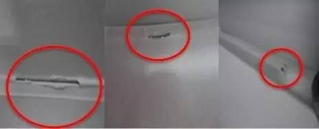
10. Bad profile
Cause:
a. There is a problem with the incoming material. _cc781905-5cde-3194 -bb3b-136bad5cf58d_
b. Caused by impact during processing.
c. Blades and files are scratched in the cleaning process.
Precautions:
a. The operator must have the ability to self-check the materials used. _cc781905-5cde-3194 -bb3b-136bad5cf58d_ _cc781905 -5cde-3194-bb3b-136bad5cf58d_ _cc781905-5cde-3194- bb3b-136bad5cf58d_
b. Pay attention to the operation during the framing process, and often check the effect after framing. _cc781905-5cde-3194 -bb3b-136bad5cf58d_ _cc781905 -5cde-3194-bb3b-136bad5cf58d_
c. Hold it steady when lifting the component.
d. Be careful with blades and files when cleaning.
e. The technician should manage and confirm the size of the frame after installation.
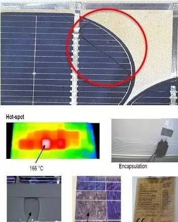
11. Glue bubble
Cause:
a. Glue bubbles are mainly caused by bubbles in the collagen material or unstable air pressure of the air gun.
b. The main reason for the gap is the non-standard glue method of employees.
Component Impact
Where there are gaps, rainwater will enter. After the rainwater enters, the components will heat up when working, which will cause delamination.
Precaution:
a. Strengthen personnel skills training and enhance self-inspection awareness.
b. The method of personnel gluing should be standardized.
c. Strict inspection by cleaning personnel.
d. Pay attention to adjusting the air gun pressure.
Source: Photovoltaic Standards and Technology